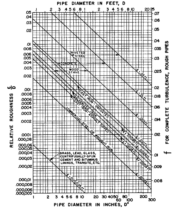
Pipe and Duct Systems Table A.1 Average roughness of commercial pipes. Table A.6 Data for copper pipes Weight per Linear Foot of Gallons of Pipe and Water per Water (lb) Linear Foot Diameter (in.) Material Nominal Inner Outer Copper Type L 1/4 0.315 0.375 0.16 0.004. The roughness is actually a measurement of all the asperities at the surface of a material, especially a pipe where it will oppose the flow of fluid. The following table is summarizing usual pipe roughness for many materials used for piping or ducts.
Pressure losses distributed in the pipes |
The calculation of the linear pressure loss, that corresponding to the general flow in a rectilinear conduit, is given by the following general formula:
- Dp= pressure loss in Pa
- L=friction factor (a number without dimension)
- p =density of water in kg/m3
- V=flow rate in m/s
- D=pipe diameter in m
- L=pipe length in m
The expression above shows that calculations of pressure losses rest entirely on the determination of the coefficient L.
| Flow type |
The nature of the type of flow of a fluid is determined by the value of the Reynolds number.
The various types of flows are visualized by the chart of the diagram of Moody using the Reynolds number for the x axis and the factor of friction F for the y axis.
The mode of flow of a fluid is characterized in 3 forms:
| Laminar mode | Reynolds number lower than 2000 indicates than the flow is calm and regular |
| Turbulent mode | Reynolds number higher than 4000 indicates than the flow is in the form of swirl and of movement. |
| Zone critique | Reynolds number located 2000 and 4000 indicates that the flow is unstable between the laminar mode and the turbulent mode. |
| Calculation of the Reynolds number |
The Reynolds number is no dimensional (thus without units). It combines 3 significant characteristics of the flow and the fluid: speed, density and viscosity. The diameter is necessary to make the number no dimensional. One calls the diameter the characteristic length. A Reynolds number of 2000 or less indicates a flow in laminar mode while a number of 4000 where more a turbulent flow indicates.
The Reynolds number is defined is:

According to kinematics viscosity | According to dynamics viscosity |
(legal System (S.I) in m²/s = 1000000 centistokes or mm²/s) |
|
Reynolds number is inversely proportional to kinematics viscosity.
The viscosity of a fluid is a characteristic which makes it possible to determine resistance to the movement of the fluid. The higher kinematic viscosity will be and the more difficult it will be to move the fluid in the pipe.
Kinematics viscosity (v is the ratio of dynamic viscosity on the density of the fluid.
Kinematics viscosity in m2/s | kinematics viscosity in mm²/s (or centistokes) |
| |
| Loss pressure |
Laminar flow (Re £ 2000)
In rate of laminar, the nature or the surface quality of the interior walls of the lines does not intervene in the calculation of the pressure loss.
The loss pressure is determined by the following function:
- L=friction factor (a number without dimension)
- Re=Reynolds number

The laminar flow meets in practice only in the transport and the handling of the viscous fluids, such as the crude oil, fuel oil, oils, etc.
Turbulent flow (Re > 2000)
In the critical zone, i.e. between 2000 and 4000 Reynolds the formula of computation employed will be treated in the manner that in situation of mode of turbulent flow.
In rate of turbulent, the factor of friction is translated by the formula of Colebrook considered as that which translates best the phenomena of flow into turbulent mode.
It is noted that this formula is in implicit form; consequently search can be done only by successive approaches (iterative calculation)
With:
- L=friction factor (a number without dimension)
- D =pressure loss coefficient.
- k=index of roughness of the pipe.
- d=pipe diameter in mm.
- Re=Reynolds number.
Usual value index of roughness (k) in mm | ||||
Nature of interior surface | Index roughness K | |||
1 | Copper, lead, brass, stainless | 0,001 to 0,002 | ||
2 | PVC pipe | 0,0015 | ||
3 | Stainless steel | 0,015 | ||
4 | Steel commercial pipe | 0,045 à 0,09 | ||
5 | Stretched steel | 0,015 | ||
6 | Weld steel | 0,045 | ||
7 | Galvanized steel | 0,15 | ||
8 | Rusted steel | 0,1 to 1 | ||
9 | New cast iron | 0,25 to 0,8 | ||
10 | Worn cast iron | 0,8 to 1,5 | ||
11 | Rusty cast iron | 1,5 to 2,5 | ||
12 | Sheet or asphalted cast iron | 0,01 to 0,015 | ||
13 | Smoothed cement | 0,3 | ||
14 | Ordinary concrete | 1 | ||
15 | Coarse concrete | 5 | ||
16 | Well planed wood | 5 | ||
17 | Ordinary wood | 1 | ||
| Influence rate of antifreeze (glycol) |
In the case of an addition of antifreeze (glycol) to water, kinematics viscosity (into centistokes) varies in the following way:
- t = temperature at 0°C
- a = percentage of glycol
Last update:
Schedule 40 Steel Pipe Roughness
For each pipe material either a single pipe roughness value or a range of roughness values is normally provided by the manufacturer. The roughness value, usually denoted as e, is used in the calculating the relative roughness of a pipe against the size of its diameter.Absolute Roughness
Roughness Of Copper Pipe
The roughness of a pipe is normally specified in either mm or inches and common values range from 0.0015 mm for PVC pipes through to 3.0 mm for rough concrete pipes.
Relative Roughness
Relative Roughness Of Copper Nickel Pipe
The relative roughness of a pipe is its roughness divided by its internal diameter or e/D, and this value is used in the calculation of the pipe friction factor, which is then used in the Darcy-Weisbach equation to calculate the friction loss in a pipe for a flowing fluid.
Pipe Materials and Common Pipe Roughness Values
| Material | e (mm) | e (inches) |
| Concrete | 0.3 - 3.0 | 0.012 - 0.12 |
| Cast Iron | 0.26 | 0.010 |
| Galvanized Iron | 0.15 | 0.006 |
| Asphalted Cast Iron | 0.12 | 0.0048 |
| Commercial or Welded Steel | 0.045 | 0.0018 |
| PVC, Glass, Other Drawn Tubing | 0.0015 | 0.00006 |
Pipe Materials and Pipe Diameter Database
Our Pipe Flow Expert software comes with its own database of pipe materials and pipe diameters, which includes the pipe roughness values and standard material schedules of many types of pipe. Users can also add their own pipe data for any material and any pipe size if required.
Pipe materials in the Pipe Flow Expert pipe database include Cast Iron (Class A,B and C), Copper Tube (Type X,Y,K,L,M), HDPE (SDR 7.3 to SDR 26), PVC (Schedule 40, 80, and CL100 to CL315), Stainless Steel (Schedule 5s, 10s, 40s), Steel (Schedule 40,80,160) and more.
You can download Pipe Flow Expert for a free trial and see how it makes it easy to draw, design and calculate the flows and pressure drops in your pipe system.